top of page

All posts

Stay up-to-date with all the latest posts and information from The Pixel Farm, including details on the newest build updates and comprehensive articles covering everything you need to know.

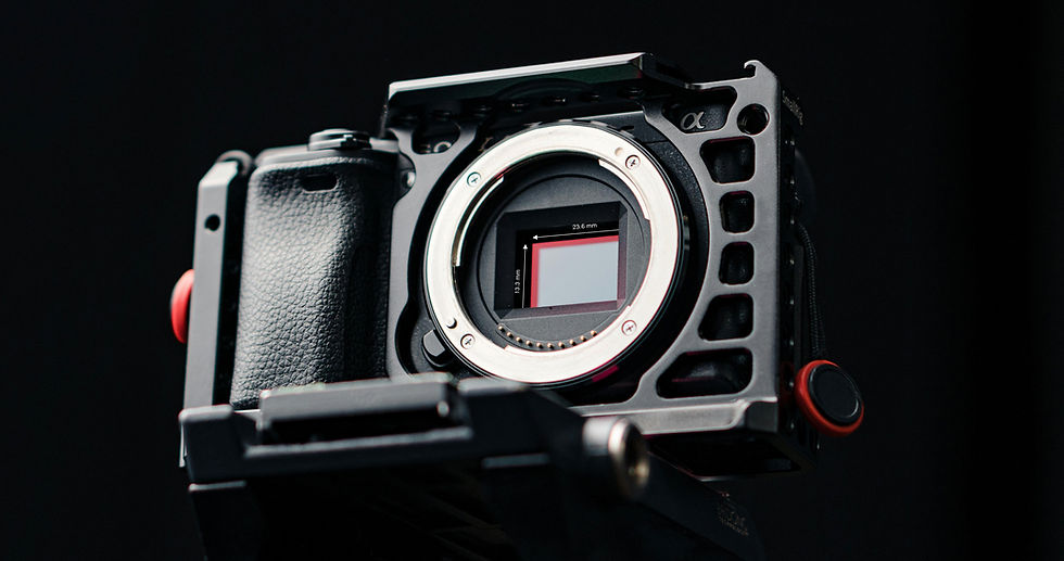
A sony mirrorless camera with sensor revealed

Navigate the learning article


Intro

What exactly is sensor size, and why does it matter for VFX, particularly when calculating the field of view for camera tracking?


This post explores the intricacies of sensor size. We’ll demystify key terminology, including "full-frame equivalent," "windowed," and "cropped" sensors. We'll also examine how metadata and other resources can help you out of a tight spot if you don’t have the info. By understanding and applying these concepts, you can gain greater control over your camera tracking projects.


What is Sensor Size?

So, perhaps a good place to start is defining what we mean by sensor size. Sensor size refers to the physical dimensions of a camera's imaging sensor—the part that turns incoming light into digital images. Usually, the height and width are measured in millimetres (mm); it is where the lens projects an image to be captured and converted into a digital signal. Sensor size affects how much of the lens's image is recorded, influencing the field of view, depth of field, and overall image quality. 


How do I find out the size of a camera sensor?

While a quick Google search will provide the necessary information for most professional cine and mirrorless camera systems, it is worth delving deeper into the manufacturer's website to find the exact size. However, remember the considerations that will be discussed later in this article when finding out the sensor's 'actual size'. If a simple search doesn't yield results, the following links lead to excellent websites that cover the essential details you may need.
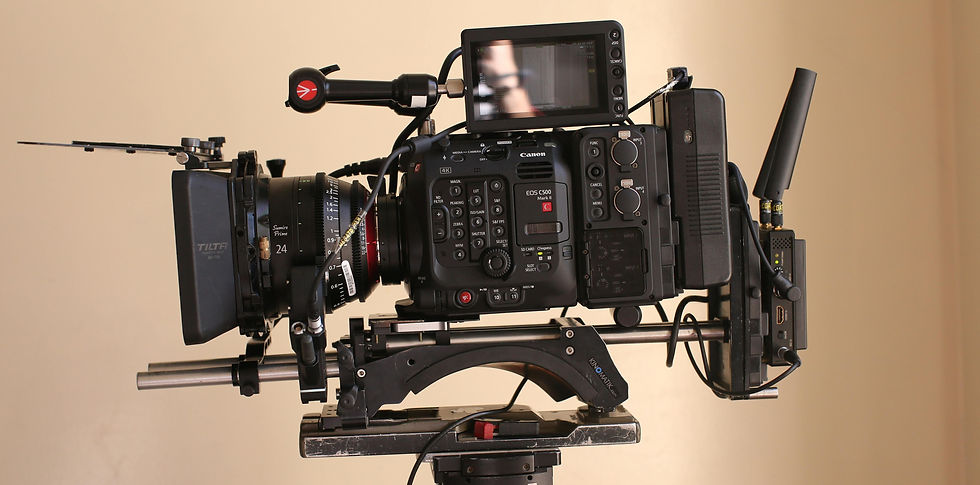

A high end cinema super 35 camera rigged for shooting

VFX camera database 

The VFX Camera Database is a valuable resource that offers an extensive, mostly up-to-date collection of professional and prosumer cameras. What sets this site apart is its inclusion of detailed measurements, not only for the full active sensor area but also for windowed sizes in different recording modes. 


DXOMARK 

This website is a database primarily focused on testing camera sensor performance. However, under the specifications tab, it also provides key details like the actual sensor size and other useful data for matchmoving, such as rolling shutter performance. This resource is especially helpful for tracking phone footage, as it includes information on most of the latest phone cameras, including sensor sizes and field-of-view equivalence. 


CINED

CINED is a production-focused website offering in-depth testing and reviews of the latest camera gear. While it primarily focuses on sensor performance, much like DXOMARK, it also provides valuable details on sensor size and windowing for various popular camera systems, including some phones and mirrorless cameras—making it a useful resource for camera tracking tasks.


Why is ‘Sensor Size’ important for camera tracking?

Camera tracking applications like PFTrack require the camera's field of view (FoV) to accurately track and solve a shot. The FoV is determined by both the lens's focal length and the sensor size. However, precise knowledge of the sensor size remains crucial for ensuring the virtual camera accurately replicates the real-world camera's perspective and movement. Without this, discrepancies in scale, position, and motion can misalign digital assets, disrupting the realism of the final shot.


Sensor Size Considerations


Loose terminology for the sizing of an imaging sensor

You’ve probably come across terms like Super35, Full Frame, and large format to describe the size of an imaging sensor in cine or still cameras. While it might seem straightforward to search "What is the size of a Super35 sensor?" and rely on the results, the information can often be inconsistent due to manufacturers' generalised and imprecise terminology.


To illustrate, suppose we have a camera with a 24mm focal length, and the camera in question is a Sony PMW-F3, which uses a "Super35" sensor. If we rely solely on Google's definition of Super35 based on the traditional film format, we might calculate the following horizontal and vertical field of view:
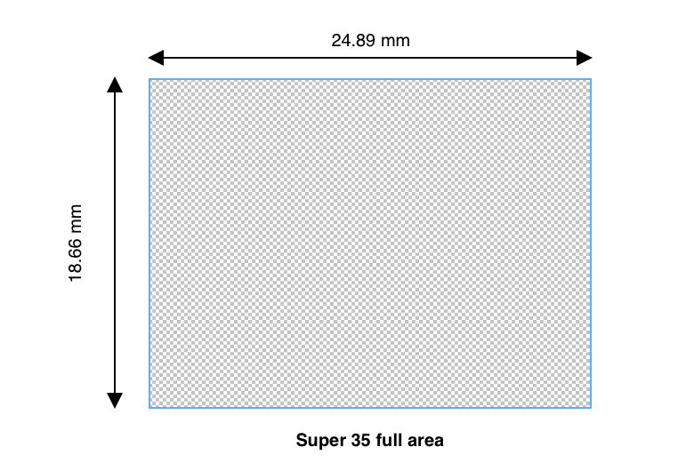

A graphic showing the dimensions of the film format super 35


Super35 format size: 24.89 mm x 18.66 mm


Horizontal FoV: 54.82°


Vertical FoV: 42.49


Delving deeper into the manufacturer's sensor specifications reveals that its size is not identical to a true Super35mm sensor; instead, it has been rounded up and features a different aspect ratio. This discrepancy impacts calculations, resulting in a field of view that is 2.46° narrower horizontally and 11.52° narrower vertically than anticipated.
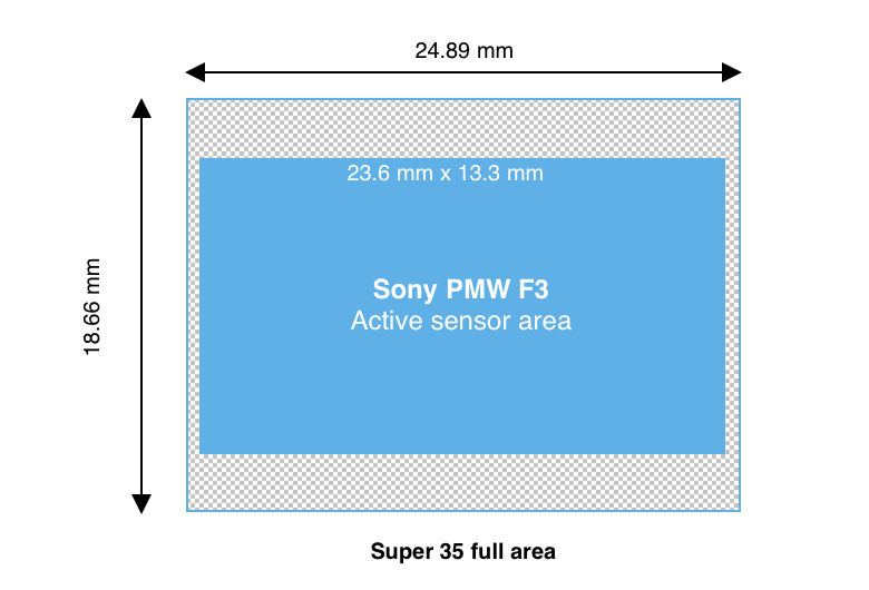


a graphic showing the size comparison of the PMW F3 sensor over the Super 35 format


Actual sensor size: 23.6 mm x 13.3 mm


Horizontal FoV: 52.36°


Vertical FoV: 30.97°


While this may not seem significant, even small sensor size discrepancies can impact your solve's overall accuracy. This is especially true for smaller sensors, such as those used in drones and cameras built into phones, where precise field of view (FoV) calculations are critical. 


The term "Large Format" adds further confusion, as it has come to refer to any sensor larger than 36x24mm without clearly defined upper limits, complicating efforts to strictly define sensor size for camera tracking. The situation becomes even more complex when considering sensor crop and various windowed shoot modes. 


Windowed, Scaled, and Crop Modes: Effects on FoV

If you have looked up the size of the image sensor in the camera that shot your clip and entered the information, and things just don’t seem to be making sense or working, it might be because your camera is shooting in a mode that affects the FoV of your image. 


Full Area Vs Active Area

The difference between the active imaging area and the full sensor area lies in how much of the sensor's surface is actually used for capturing an image versus the total physical size of the sensor itself.


Full Sensor Area: This refers to the total physical dimensions of the sensor, including all of its pixels and regions, whether they are used for capturing an image or not. The full sensor area accounts for every part of the sensor's surface, including pixels reserved for other functions (such as calibration or stabilisation) or areas that may be masked out during image capture.


Active Imaging Area: This is the portion of the sensor that is actively used to capture an image. It defines the region where incoming light is collected and converted into a digital image. Due to manufacturer-specific design choices, cropping, or masking, the active imaging area can be smaller than the full sensor area. This distinction is important in applications like camera tracking, as it directly affects how the image is projected onto the sensor and impacts field-of-view calculations. When entering information about the sensor in your camera, it is always important to use the ‘Active Imaging Area’ over the ‘Full Sensor Area’ where possible for best accuracy.


Windowed Sensor Mode

Sensor windowing occurs when only a portion of the imaging sensor is used to capture an image, effectively "cropping" the sensor's active area. This is common in cine cameras when recording RAW and selecting a resolution or format other than the sensor's native resolution. Instead of resampling the full sensor, the camera activates a smaller portion of it, which alters the field of view. Similarly, sensor windowing is often used to achieve very high frame rates, as processing data from a smaller sensor area reduces the hardware's workload. 


For instance, the RED MONSTRO 8K sensor, measuring 40.96 x 21.6 mm, utilises its full area when shooting at its maximum resolution of 8K (8192 x 4320). However, the camera applies sensor windowing to achieve lower resolutions, using only a portion of the sensor’s area. 


A graphic showing the various windowed sensor sizes of the RED Monstro 8K sensor

RED MONSTRO Windowed shooting modes: 

6K shooting mode (6144 x 3240), area is 30.72 x 16.20 mm

5K shooting mode (5120 x 2700), area is 25.6 x 13.5 mm

4K shooting mode (4096 x 2160), area is 20.48 x 10.80 mm


Sensor windowing may also be necessary when using lenses for smaller imaging circles, such as a Super35 (31.1mm) optic on large format sensors).
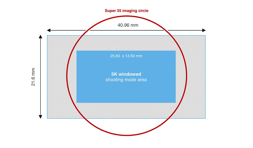

A graphics of a RED camera sensor using the 5K Super 35 windowed mode to utilise the imaging circle of Super 35
When using optics designed for the Super 35 format, the RED camera can use the 5K Super 35 windowed mode

Fortunately, PFTrack allows you to input the full area of a sensor and account for any windowing that may be happening with your camera using a separate input for the windowed area.


An image showing PFTrack's interface demonstrating the various windowed sensor modes


Scaled Sensor Mode

Sensor scaling is a simpler concept compared to sensor windowing. It involves resampling the image captured by the entire sensor area to a lower resolution while preserving the full active sensor area on one or more axes. 


Full Area Resampling

Full-area resampling takes the image captured by the entire sensor and downsamples it to a lower resolution without altering the active area or the FoV. For example, a sensor with a native resolution of 3840x2160 might be resampled to 1920x1080, maintaining the full sensor area while reducing the pixel count. 
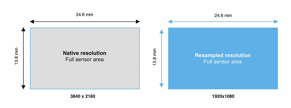

A graphics showing full area resampling of an image sensor
Despite resampling from UHD to HD, the sensor's full FoV is maintained

Aspect

Sensor scaling can also account for changes in aspect ratio. For instance, a sensor with a native aspect ratio of 1.78:1 (16:9) may crop or scale the image at the top and bottom to produce a 1.85:1 aspect ratio while maintaining the full sensor width and horizontal FoV. You can enter the sensor's width, and PFTrack will calculate the height automatically. Changing aspect scale can also happen vertically; for example, if you have a native 1.85:1 sensor, the scaling may crop the sides to reach a 1.78:1 aspect ratio (see anamorphic).


A graphics showing sensor scaling to change the aspect.
Camera with a native 1.78:1 aspect sensor with a 1.85:1 ‘scaled’ sensor mode active


Anamorphic

Anamorphic scaling preserves the full sensor height and vertical FoV, while the sides are scaled/cropped to achieve the desired anamorphic recording ratio, such as 1.33:1. You can enter the sensor's height, and PFTrack will calculate the width automatically. 


A graphic showing a sensor being scaled to allow the use of anamorphic lenses
RED VV Raptor shooting in its “Scaled” 8K 6:5 anamorphic 2X mode

It's important to note that resampling a 3840x2160 resolution sensor using the full sensor area to 1920x1080 is not the same as using a 1920x1080 windowed shoot mode, where only a portion of the sensor's full area is utilised. The two methods will result in very different fields of view (FoV).


Metadata

A key advantage of using an application like PFTrack is its ability to read metadata from formats like DPX and EXR and many camera RAW files. But why is this important for determining a camera's sensor size? Metadata often contains critical details, including the camera model and shooting mode, which can help quickly and accurately identify the sensor size from the data or use it to select an appropriate sensor preset. 


an image of PFTrack's UI where metadata can be used to determine a cameras sensor size
Using Metadata in PFTrack to determine which Sensor Preset and Shooting mode to use for the clip


A multiformat sensor?

Don’t worry this sounds more complicated than it is. The term refers to using a slightly larger sensor than standard, allowing the camera to “window” the sensor to achieve various aspect ratios, formats, and frame rates directly in-camera rather than capturing the full sensor area and cropping it later. 
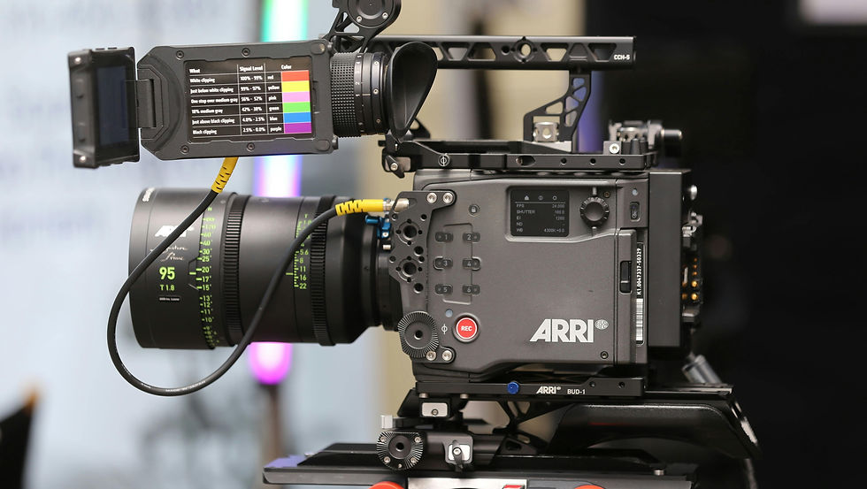

An image of an ARRI Alexa 35 cinema camera, which has an Open Gate sensor size of 27.99 x 19.22 mm
ARRI Alexa 35 cinema camera, which has an Open Gate sensor size of 27.99 x 19.22 mm

A prime example is the ARRI Alexa 35, which utilises its full active sensor area of 27.99mm x 19.22mm in Open Gate mode and dynamically windows/scales the sensor to accommodate common standards at the correct measurements.
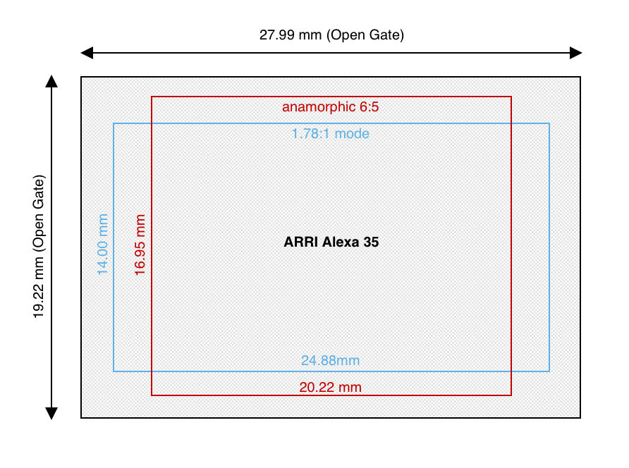
A graphic showing the Arri Alexa 35's multiformat sensor and the various windowed shoot modes overlaid

For instance, the 1.78:1 mode uses a 24.88mm x 14.00mm area, while the anamorphic 6:5 mode employs a 20.22mm x 16.95mm area. This adaptability ensures the sensor can handle diverse applications, leveraging its entire surface or specific regions to deliver the desired field of view and resolution for each format using the correct imaging circle.


Full-frame equivalent or the actual sensor size?

If you've searched everywhere but can’t find information about your sensor size, you might still have a "full-frame equivalent" focal length to work with.


The term "full-frame equivalent" refers to the focal length of a lens on a camera with a sensor size other than full-frame (36mm x 24mm) that produces a similar field of view to a lens on a full-frame camera. Essentially, it allows for comparing how a lens on a smaller sensor camera would behave if mounted on a full-frame camera. Manufacturers often use full-frame equivalence to simplify marketing, particularly in systems with integrated optics, such as handheld gimbals and drones. However, this approach can obscure the true sensor size.


So, can you rely on full-frame equivalence instead? The answer is both yes and no. For example, the DJI Osmo Pocket 3 does not readily disclose its sensor size, but it states that the combination of its sensor and optics produces a full-frame equivalent field of view to a 20mm lens. Using this information, you could input the horizontal size of a full-frame sensor (36mm) and a 20mm focal length to estimate the field of view. However, this assumes the 20mm equivalence is precise. Manufacturers often round up or down to the nearest common photographic focal length for simplicity. While such minor differences are negligible for everyday filming or photography, they can lead to inaccuracies in precision workflows like camera tracking.


Full-frame equivalence can provide a starting point if no other data is available. However, be cautious, as it might not deliver the accuracy required for tasks like camera tracking.


Wrap Up

In conclusion, we hope this post has clarified some of the challenges in identifying the correct sensor size for your camera while providing a foundation in key concepts and terminology.


Whether working with high-end cine cameras or smaller devices like drones, understanding and applying sensor size information is essential for accurate tracking. Leverage resources like the VFX Camera Database and DXOMARK to quickly access precise sensor specifications for your projects.


Finally, remember that PFTrack offers powerful tools for calibrating your camera body, and the Auto camera model can be a reliable fallback when all else fails. Armed with this knowledge and the right tools, you'll be well-equipped to tackle your next camera tracking challenge with confidence.


Links

To explore PFTrack and the topics discussed in this article, you can download it using the links below and start exploring in discovery mode for free.


Updated: Mar 17


image showing a manual feature track

What’s the difference between automatic and manual tracking? Which is better? When should I use one instead of the other? And how do the differences affect the camera solver?


In this article we’ll take a look at some of the more technical details of how trackers are used in #PFTrack, and suggest some ways of getting the most out of PFTrack’s advanced feature tracking tools.


What is a tracker?


A tracker defines the location of a single point in 3D space, as viewed by a camera in multiple frames. In PFTrack, trackers are generally created using two nodes: Auto Track and User Track. The Auto Track node is able to generate a large number of estimated trackers automatically, and the User Track node provides manual tracking tools for precise control over exactly where each tracker is placed in each frame.


PFTrack's node tree showing the Auto Track and User Track nodes

Trackers form the backbone of any camera solve, and they are used to work out how the camera is moving along with its focal length and lens distortion if they are unknown. But how many trackers do you need, and what is the best way of generating them?


How are trackers used to solve the camera?


When solving for the camera motion in a fixed scene under normal circumstances, PFTrack needs a minimum of 6 trackers to estimate the motion from one frame to the next. This is the bare minimum, however, and we generally recommend using at least 8 or 10, especially if you’re not sure of the focal length, sensor size, or lens distortion of your camera. Using a few more than the minimum can also help smooth out transitions in the camera path from one frame to the next, where one tracker might vanish and another one appears in the next frame.


A point cloud of solved feature points with a virtual camera following the camera path

Trackers should be placed at points that are static in the real world (i.e. do not move in 3D space), such as the corner of a window frame or a distinguishable mark in an area of brickwork. This allows the 3D coordinates of the point to be estimated, which in turn helps to locate where the camera is in each frame.


To help with estimating camera motion, trackers also need to be placed in both the foreground and background of your shot, especially when trying to estimate focal length, as this provides essential parallax information to help the solve. It’s also important to have trackers placed in as many parts of the frame as possible, rather than just bunching them together in a single area. Think of your camera’s grid display as dividing your frame into a 3x3 grid of boxes - try to have at least one tracker in each box in every frame, and you’ll have good overall coverage.


An example of good manual user track placement in a clip


Not every tracker is equal


We’ll get into the details of how to generate trackers shortly, but before we do it’s important to understand that not every tracker is considered equally when solving the camera. The most significant distinction is whether a tracker is defined as being a soft or hard constraint on the camera motion.


Hard constraints mean the placement of the tracker in every frame is assumed to be exact. If you’ve generated trackers manually using a User Track then these will be set as hard constraints by default. The solver will try to adjust the camera position and orientation to make the tracker’s 3D position line up with its 2D position exactly in every frame when viewed through the camera lens.


A table demonstrating the difference between hard and soft constraints


On the other hand, trackers that are generated automatically with the Auto Track node are marked as soft constraints and don’t have to be placed exactly in every frame. The camera solver is able to recognise that some errors in the 2D positions exist and ignore them. These are often referred to as “outliers” and might correspond to a temporary jump in the tracker position for a couple of frames or the subtle motion of a background tree in the wind, resulting in the 3D location of the tracking point changing from frame to frame.


So now that we’ve explained some of the details about how the camera solver uses trackers, what is the best way of generating them? Auto-Track? User-Track? Or both? Ultimately, the answer to this comes down to experience with the type of shot you’re tracking, how much time you have to spend on it, and the final level of accuracy you need to complete your composite.


To get started, here are some guidelines that should help you quickly get the most out of PFTrack’s tools.


Automatic feature tracking


If you have all the time in the world to track your shot, then of course, manually placing each tracker in every frame is the way to go, as this ensures each one is placed exactly where it should be.


Alternatively, automatic feature tracking is a way of generating a large number of trackers very quickly, but because the tracking algorithm is attempting to quickly analyse the image data and work out the best locations to place them, not every tracker is going to be perfect.


Automatic feature tracks in action

The Auto Track node picks out a large number of "interesting" points and corners in each image, and tracks those points bi-directionally between each pair of frames (i.e. from frame 1 to 2 and then from 2 back to 1). It compensates for any differences in exposure or lighting whilst doing this, and also tries to ensure that jumps and inconsistencies in the motion of each point between frames are avoided wherever possible.


After all the points are tracked, it filters them down to select around 40 trackers in each frame (using the default settings). The trackers are chosen in a way that tries to distribute them evenly over the image area whilst also ensuring tracks with the longest length are used wherever possible, so each tracker is visible in many frames of the clip to help out the camera solver.


However, these trackers may end up being placed on objects that are moving independently from the camera, or at other locations that cannot be resolved to a single point in 3D space. For example, so-called “false corners” that result from the intersection of two lines at different distances from the camera can often be indistinguishable from real corners when looking at a single image.


Whilst the camera solver will ignore these outliers to a certain extent, having too many trackers falling into these categories can adversely affect the solve, so how should you deal with them?


Identifying errors


Whilst PFTrack will attempt to detect when tracking fails, not every glitch can be easily detected, especially when your shot contains motion blur or fast camera movement. It’s always worth reviewing automatic tracking results to check whether there are any obvious errors.


For example, the motion graphs in the Auto Track node can be used to quickly identify trackers that are moving differently from the others.


Motion graph in PFTrack showing a highlighted glitch

The “Centre View” tool can also be used to lock the viewport onto a single tracker. Scrubbing forwards and backwards through the shot will often expose motion that is subtly different from the background scene, which may indicate a false corner or other gradual object movement.


To fix or disable?


So now you’ve identified some trackers that need some attention. What’s next?

The Auto Track node is built to quickly generate your tracking points, and the User Track node provides you with full control to address any issues and manually place trackers yourself.


Fixing a tracking point is easy enough - just use the Fetch tool in the User Track node to convert the automatic tracker into a manual one, and all the tools of the User Track node are available to you to adjust the tracker as needed.


Quick video demonstrating how to manually adjust Auto Tracks


You can manually correct every single one of your automatic trackers if you wish, but as we mentioned earlier, the Auto Track node generates many more trackers than are actually needed to solve the camera motion. This means you may well be spending a lot of time unnecessarily correcting trackers if you have a particularly tricky shot.


It can often be just as effective to quickly disable the bad trackers, especially if time is short. This is certainly the case if you’ve only got a few outliers, and also have other trackers nearby that don't need fixing.


Quick video demonstrating how to disable Auto Tracks


You could also use the masking tools in PFTrack to mask out any moving objects before automatic tracking, although it’s important to weigh the time it will take you to draw the mask against the time it takes to identify and disable a handful of trackers afterwards.


Remember that trackers should be distributed over as much of the frame as possible, and we recommend a minimum of around 10 in each frame, so keep this in mind when disabling. If you end up having to disable a lot and are approaching single-figures, then maybe a different strategy is going to be necessary: supervised tracking.


Supervised feature tracking


Ultimately, a lot of shots will need some level of manual, or 'supervised', tracking using the User Track node.


A image of a supervised feature track

This is especially important if you’re tracking an action shot with actors temporarily obscuring the background scene. One limitation of automatic feature tracking is that it can’t connect features from widely different parts of the shot together if something is blocking their view or the feature point moves out of frame for a significant length of time.


In these cases, human intervention is often necessary, and this is where the User Track node comes into play, allowing you to create trackers from scratch to perform specific tasks.


For example, you may have a shot where the camera pans away from an important area for a few seconds and then pans back. Or an actor may walk in front of an important point before moving out of frame. In these cases, you want to make sure the 3D coordinates of points at the beginning are the same as at the end. Creating a single tracker and manually tracking over frames where it is visible (whilst hiding the tracker in frames where it is not visible) will achieve this goal.


PFTrack's UI showing a gap in the tracked feature

The same guidelines apply when creating tracking points manually - try to distribute them over your entire frame, and make sure that you’ve got a good number of trackers in each frame.


Also, try not to have many trackers stop or start on the same frame (especially when they are treated as hard constraints), as this can sometimes cause jumps in your camera path during the solve that will require smoothing out. If you do, adding a couple of “bridging” trackers elsewhere in the image that are well tracked before and after the frame in question can often help out.


Wrap Up


Hopefully, this article has shed some light on things to consider when tracking your points. In the end, this all comes down to experience, and as you track more shots, you’ll get a better feel for when to use specific tools, and whether to start with supervised tracking straight away or give the Auto Track node a go first of all. 


If you are using automatic tracking, you can easily place an empty user track node between the Auto Track and Camera Solver to hold any user tracks that need adjusting, or any you need to create manually.


Also, don’t worry about getting every tracker perfect before you first attempt a camera solve. It’s often possible to try auto tracking first and see where that gets you, then consider how to address any problems and add a few user tracks to help the solver out.


PFTrack lets you adjust and change your trackers however you want. If you’ve almost got a solve but can see a bit of drift in a few frames, try creating a single manual tracker over those frames in a sparsely populated area of the image, then solve for the 3D position of that tracker alone, fix your focal length and refine your solution - you don’t have to solve from scratch every time.


If you’re interested in some more details, stay tuned for a follow-on post that will explain some of the finer details of the Camera Solver node, including how to detect and handle ambiguous camera motion, how to bootstrap solves using feature distances, and exactly what an initial frame is and when to change them.


Download now and explore PFTrack's powerful features in discovery mode here!


bottom of page