top of page

All posts

Stay up-to-date with all the latest posts and information from The Pixel Farm, including details on the newest build updates and comprehensive articles covering everything you need to know.

Updated: Jul 17, 2024


Matchmoving is becoming more and more of an automated process of tracking and solving. But there are still cases where the keen eye of the matchmove artist can save time by spotting potential issues that could derail your tracks and solve them. This post will list what to look for to identify which clips need your attention.


1 — Lens distortion

Lens distortion is an optical aberration that causes straight lines to appear curved in photos or films, and it is easy to see how this can cause issues for the matchmove artist.

Trackers along a straight line in the real world are no longer on a straight line in the resulting distorted image, and the effect on a camera track can, at best, produce false positives or, in the worst case, cause the 2D tracking to fail altogether.


Lens distortion can be recognised by looking for straight objects at the edges of the frame, such as the beam in the image below.


Due to the 3D representation of trackers that should be in a straight line now being on an arc and not truly reflecting the real-world scene, the camera solve will fail when it becomes impossible to line the virtual camera up with the distorted tracking points.


Fix?

Film and television audiences are used to a certain amount of lens distortion in their viewing experience, and any CG must be distorted in the same way as the background plate to blend in perfectly. The trick is to undistort the image plate BEFORE carrying out any tracking/matchmove operations, then use the calculated distortion models further into the VFX pipeline.


All good matchmoving software has distortion pipeline tools built in, which allow the distortion of the background plate prior to tracking and the ability to pass the distortion metrics (more commonly supported through ST Maps) further into the VFX pipeline, usually the composting software.


2 — Rolling shutter

Like lens distortion, rolling shutter results from limitations of the image capture technology employed to shoot the footage. The effect of rolling shutter occurs when different lines of the image sensor are recorded at slightly different times, which commonly happens with CMOS sensors.


The effects of shutter roll are most noticeable with whip-pans or rapid translations. If the camera sensor records the image line by line during such fast movements, different parts of a frame are recorded at different times and from different camera locations.

Unfortunately, a bad rolling shutter can render your footage almost unusable for motion effects such as tracking and titling, not just because the distorted image will cause tracking to fail but also because it is virtually impossible to match any form of CG to the unpredictable distortion.


Fix

The best fix is to sidestep any capture technology that produces this particular effect and opt for a better-quality device. However, the fix-it-in-post mentality that can sometimes occur means the VFX departments get what they are given. Fortunately, there are fixes out there.


To make a usable image, you must reverse-engineer a unique camera position for a single frame when no such position exists. Shutter roll must be treated before the tracking, so matchmoving applications can rely on all scanlines of a single frame to represent the same time and location.


Shutter roll became such a big issue that numerous plugins from third-party vendors are available to provide fixes, with varying results. PFTrack has a tool built in to undistort the background, which can be passed down the tracking tree, and other matchmove apps can deal with footage similarly.


After undistorting the rolling shutter and tracking, you will need to provide the resulting undistorted background plate further into the VFX pipeline for any compositing, etc. to be carried out. Unlike lens distortion, it is not usual to re-introduce the distortion characteristics.

PFTrack’s Shutter Fix node can be used to reduce the effects of rolling shutter.

additional rolling shutter ref — https://en.wikipedia.org/wiki/Rolling_shutter


3 — Lack of features

Matchmoving applications rely on tracking static object features within the image. From the way these features move through an image sequence, the matchmoving application reverse engineers how the camera was moved to film it and even some properties of the camera itself, such as focal length. Ideally, the features to be tracked will be well distributed over the entire 2D image, as well as the 3D space of the scene.


So, the key to a successful auto-track and camera-solve is to have plenty of well-spread, trackable features in your clip. A trackable feature can be virtually anything that stands out in the image, such as the corner of a window.


No background detail

Uniform backgrounds, such as a green screen used in many VFX shots, however, don’t have as many features as in the example above. There is nothing to track in the worst cases, such as in the clip below. This clip will require some manual work to get a working camera.


On the other hand, even green screens do have tracking markers in many cases, but due to the nature of green screens, these markers will not always sufficiently stand out.


Fix

The clip can be altered in many cases to make it more visible, as in the example above.


Motion blur

Another common case that can result in a lack of trackable features is motion blur caused by a fast-moving camera. As such, motion blur makes it harder for an algorithm to locate trackable features. Any features that may be found are also harder to track due to the fast camera motion.


Fix

You may be able to recover enough detail for a track through image processing, but in many cases, clips with heavy motion blur will require manual trackers to get the best result.


4 — Incorrect features

In some cases, there may be plenty of features to track, yet these features would not feed the correct information to the matchmoving applications. To be of any use to solve for a camera, trackers must represent the same real-world 3D position throughout the clip. Below are some examples of where this is not the case.


Too much movement

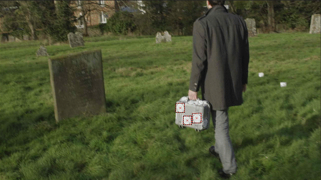
One obvious example of trackers not sticking at what represents the same real-world position is when there is movement inside the shot, such as moving cars or people. In an exterior scene, these could also be branches of trees subtly swaying in the wind. Even though they may appear not to move very much, they can pose a problem if too many trackers are on them.


The clip below shows an example of a moving person. While these trackers cannot be used to solve a camera, they would still be helpful to solve the object’s motion in a later step.


Fix

If a shot contains too much motion, the moving objects may have to be masked out before tracking or any trackers on such objects removed before feeding them into the camera solver. In many cases, however, the consistency parameter in PFTrack’s Auto Track node can automatically eliminate independently moving trackers.


False corners

Another example where trackers do not provide helpful information, neither for camera nor object tracks, is false corners. False corners occur when two objects at different distances from the camera overlap. Tracking algorithms could interpret the intersection of these two objects as a trackable feature. Solving algorithms, however, expect features to represent the same 3D real-world position, which is not the case for false corners.


Fix

This issue requires an observant operator to spot suspicious trackers. Turning on tracker motion prediction in PFTrack’s Auto Track or Auto Match node may help avoid tracking false corners, as can the Auto Track node’s consistency setting.


5 — No Parallax

Matchmoving relies heavily on parallax, the familiar effect that objects far away move more slowly than objects closer to us. For camera tracking, the application uses this knowledge to estimate the relative distance of trackers from the camera and determine how the camera moves. But there are types of shots that do not exhibit any parallax.


Locked off shots

Without any camera motion, background features will not move at all, which means features further away cannot move slower than features closer to the camera.


Zoom shots

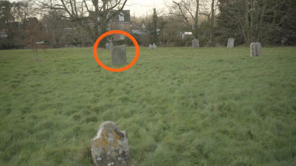
At first glance, it may look like motion, but zooming into a locked-off camera does not exhibit parallax. Zooming only magnifies a part of the image, and all objects inside that part keep their relative positions. The following example shows the different results you get from a zoom shot compared to a dolly shot, where the camera moves forward. Note how in the dolly shot, the objects move relative to each other, and, as a result, more of the circled object is revealed at the end of the shot.


Nodal pan

Nodal pans are a third example of shots that don’t contain parallax. The easiest way to imagine a nodal pan is a camera mounted on a tripod with no horizontal movement. This rotational motion of the camera does not create any parallax, as illustrated in the clip below.

While most tripod shots are not actual nodal pans, they must rotate the camera around its optical centre. They often still do not contain enough parallax to solve for accurate 3D tracker positions.


Fix

Introducing additional views of the scene, such as still images shot from a different position, will let you extract 3D data from nodal pans.


Conclusion

Spotting these issues early can help you distinguish easy-to-track shots from those that need extra care in matchmoving. The Pixel Farm’s matchmoving application, PFTrack, provides tools to help you mitigate these issues (as outlined in the fix suggestions) and solve many difficult situations.


Start now and download PFTrack today to explore its powerful features for free in discovery mode!


Updated: Jul 17, 2024


The stress levels are rising, the deadline is looming, and the shot you’re working on is taking far longer to matchmove than you first thought. Don’t worry – we’ve all been there! 

Matchmoving is a technique used to track how the camera moves through the shot so that an identical virtual camera can be reproduced inside a software package, a process crucial in visual effects for integrating and matching the perspective of CGI (computer-generated images) with live-action plates.


In this article, we examine some of the camera acquisition types commonly used for film, television, and VR and outline some key factors and limitations that can make a seemingly straightforward matchmove take much longer than expected.


Camera Acquisition

Cinema or cinema-style cameras usually have a high resolution, high dynamic range, large format sensor with RAW data recording and the ability to capture high frame rates for slow motion. Commonly used for feature films, television dramas and commercials, this type of camera offers the very peak in acquisition technology. Using an industry-standard, positive lock (PL) lens mount enables using the same cinema primes and zooms on different manufacturers’ cameras. Nearly all cine-style cameras record to common UHD broadcast and DCI spec film standards, along with non-standard raw frame sizes beyond 4K.


Super 35 and Full Frame sensors have become the standard for high-end acquisition and will be the formats you will most likely come across when matchmoving. One thing I’ve noticed is the loose definition manufacturers use to describe the size of the sensor. For example, you will see Super 35 within their marketing, referring to the motion picture film format size of 24.89mm x 18.66mm. However, if we delve deeper into the actual specifications, we will see that this description only approximates the actual physical size of the sensor plane. While slight differences in the field of view are not hugely important for camera operators, it is very important for VFX professionals such as matchmovers, compositors and 3D artists.


Slow motion can cause problems for matchmovers in certain circumstances. To achieve high frame rates, some camera systems have to window the sensor, effectively cropping it to increase the sensor’s readout performance, resulting in a reduced field of view.


This means measurements in the manufacturers’ specifications are purely the sensor size rather than the imaging area used to capture a given format. The same thing can happen when selecting a different recording standard. For example, DCI 2k resolution (2048×1080) might use more of the sensor's imaging area than HD (1920×1080), meaning HD effectively has a narrower field of view.


Factors to consider when handling footage


Resolution

Image resolution defines the amount of detail in footage or a still image. Modern high-end cine camera systems, such as those from Red and Arri, have resolutions of 6K and beyond. However, optics and sensor characteristics play a part in the fidelity of the final recorded footage. Not all 4K/HD cameras are born equal. Some use pixel binning and interpolation to arrive at a given resolution. While it’s not essential to know how this works, it is important to know that this can dramatically affect the overall quality.


In the example below, I simultaneously shot a scene in 4K (4096×2160) and HD 720p (1280×720). Notice how fine details in the stonework are visible in the 4K version, whereas they have disappeared in the 720p HD footage.


How does this affect matchmoving?

With good-quality footage, high-resolution plates can be a joy to work with. Fine details in the scene, which would have been completely lost in lower resolution formats, suddenly become a rich array of trackable features. High resolution is not without its downsides, though. Apart from the obvious increase in processing time, you’ve actually got to increase your feature sizes accordingly to avoid ending up with very small feature windows with limited useful data inside them. We can see this in the example below. The left-hand image is the feature window from the HD (1920×1080) clip and the right is from UHD (3840×2160).


Ultimately, increasing resolution does not always lead to increased tracking accuracy. Soft or poorly calibrated optics can have a similar effect on your footage.


Dynamic Range

One area with many variances is dynamic range. In simple terms, dynamic range is the range of light/brightness that a camera can see. Have you ever taken a photo with your mobile phone on a bright sunny day and wondered why the sky looks so bright, and the clouds have disappeared? This is caused by a limitation in the sensor’s ability to reproduce the brightest and darkest parts of the scene at the same time.


Some sensors are better at reproducing a range of brightness than others. I shot the image below using the same exposure settings, once with an HD cine camera and again with a mobile phone in HD video mode. Ignoring the lack of sharpness and depth of field differences for the moment, we can see the phone image has a complete lack of detail in the sky and the roof compared to the cine camera’s image. Additionally, all the detail in the foreground blinds is absent where they intersect with the sky in the phone image.


The difference in detail between the two images is that the cine camera sensor can capture two-thirds of the total brightness range in the scene, whereas the phone camera sensor can only capture a quarter of the total brightness range at best. The detail not captured by the sensor will rapidly clip to white in the highlights and crush to black in the shadows. It’s important to note that incorrect handling of recorded footage can also result in a loss of dynamic range.


Let’s look at another example below. Notice the lack of trackable detail in the shadow portion of the image on the right.


How does this affect matchmoving?

Good contrast is essential to matchmoving, but not at the expense of detail. Put simply, it’s the difference between a few trackable features and many trackable features. While tracking a low dynamic range scene is far from impossible and could potentially yield great results, having a feature-rich, high dynamic range scene can make your life much easier and get you closer to the results you desire quicker.


Rolling Shutter

There are two types of sensor readout: global shutter, which reads the image data from the sensor all at once, and rolling shutter, which reads each line of image data sequentially from top to bottom. A slow rolling shutter readout time causes the image to skew in fast motion, commonly seen on low-end cameras. 


You can see the effects of rolling shutter for yourself using a mobile phone set to video mode. Point the camera towards a vertical surface like a door frame. Record with the phone held steady for a few seconds, then gradually pan left and right with the phone, slowly increasing the rate at which you pan. When you play back the footage, you will notice that the door frame tilts as you increase the pan speed rather than being perfectly vertical as it should be. Below are some stills from the footage I recorded of a brick wall with my phone camera demonstrating the issue.


Most cameras, especially consumer and semi-professional cameras, will suffer from rolling shutter, sometimes severely.


In simple terms, rolling shutter is caused by the image being read off the sensor row by row, and by the time it reaches the bottom, the camera orientation has changed slightly. In effect, the top of the image is a slightly different point in time from the bottom. High-end cameras from Red and Arri do suffer from the effects of rolling shutter but reduce them dramatically by increasing the speed at which the image is read off the sensor.


How does this affect matchmoving?

Rolling shutter is movements where there should be none, which leads to false results when we matchmove the footage. Rolling shutters are complex problems that need fixing. Foreground elements skew to a greater degree than the background. However, advanced matchmoving software like The Pixel Farm’s PFTrack offers a solution to correct or minimise this.


Image Noise

When taking a photo in a dimly-lit environment using your camera phone, the pictures can look a bit noisy and lacking in fidelity. This is because the camera is gaining the signal by increasing the ISO in order to reach an adequate exposure level. Lower ISO values generally mean lower noise levels, while higher ISOs increase the noise levels. High-end cinema and stills cameras will perform much better in this regard than consumer-grade camera systems. They are not immune to excessive noise when using a high ISO, but they can reach a higher ISO before noise becomes a limiting factor. Underexposure of footage can have the same effect as high ISO, revealing more of the noise floor when correcting the image back to its proper exposure level.


The example below shows a crop from the shot exposed first at 800 ISO and then at 3200 ISO. Notice how quickly fine details are obscured and lack microcontrast as we increase through the range.


How does this affect matchmoving?

Noise can be a big problem during matchmoving, especially if the footage is tracked from cameras with smaller sensors in less than adequate lighting conditions. Fine details are lost due to interpolation errors in the debayering process, which we can see clearly in the 3200 ISO example above. Excessive noise can affect how tracking points are located (e.g. when auto-tracking) and how accurately they are tracked. However, a lot of noise must be present for it to be a real problem regarding matchmoving.


Compression

Have you ever been streaming your favourite series when, suddenly, the internet connection dropped, and you were left with a mess of blocks and squares, making it difficult to even make out people’s faces? This is the result of compression.


A similar effect can happen during a shoot when there is significant camera movement, and a highly compressed codec is used to record the footage. Most cameras offer an option to record to a compressed codec to save space on memory cards when longer recording durations are required. Point-of-view (POV) cameras frequently use highly compressed codecs for recording.


Modern high-end broadcast codecs will deliver images almost indistinguishable from the uncompressed version. They do this by compressing the footage just enough so that it throws away information that we are not likely to need and maintains the bits that we do need. While the footage may look great when the camera is still, this might not be the case when moving.


In the handheld panning shot example below, I recorded to a highly compressed AVCHD @28Mbps / 3.5MB/s codec. I simultaneously recorded uncompressed with the same camera as a comparison. Notice how some fine details have completely disappeared with the compressed recording in the image on the right. Additionally, the edges have become unrefined and, when viewed in motion, appear to dance around and jitter.


How does this affect matchmoving?

Camera movement is everything in matchmoving, and to give the software the best chance of finding an accurate solution, we will want to give it the highest-quality footage. Unfortunately, camera movement, or any movement, is the worst enemy of compression.


This will present itself as mosquito noise around fine detail and macroblocking around areas of movement, as we have seen in the example above. Some video codecs group frames together, comparing each other and only storing and interpolating information that has changed between frames and averaging any detail that hasn’t. Matchmoving with compressed footage is still possible and will provide adequate results, but it can take a lot longer due to errors created from false details caused by interpolation and compression artefacts. In any situation, RAW data recording is always preferable to compression.


Spherical 360 video

360 video consists of a real-world video shot with a 360-degree camera that allows viewers to change their viewing angle at any point during playback. These videos can be enhanced further with computer-generated images (CGI) in the postproduction process in the same way we would a conventional 2D production. However, this requires specialist matchmoving software and toolsets like The Pixel Farm’s PFTrack.


VR 360 cameras commonly involve two or more cameras recording at least HD. The clips from each camera are then stitched together, either internally or in post, to form a 360-degree spherical panorama that can be viewed in a desktop viewer or VR headset.


The two main types of VR camera systems are back-to-back and multi-camera rigs. 

Back-to-back rigs are simply two optics and sensors in one housing or two separate cameras placed back to back with combined optics that cover 360 degrees. The benefits of these systems are low parallax, size, ease of use and small footprint, making them perfect for situations where a larger 360 rig would not be practical. The downside is the somewhat limited resolution combined with the extreme nature of the optics can lead to aberrations and relatively soft results.


Multi-camera rigs share many of the same principles as the back-to-back systems but add more cameras to achieve better quality results. These rigs can comprise multiple cinema cameras or a single housing with many integrated sensors and optics. The distinct advantage multi-camera systems offer is due to the larger number of higher-quality cameras. The optics don’t have to cover such an extreme angle of view, which makes them less susceptible to complex distortions, aberrations, flaring and softening towards the extreme edges. Clearer, higher-resolution images with greater dynamic range will always have the potential to provide better results during the matchmoving process.


Unique factors with 360 video

360 camera systems can run into the same issues we discussed above but also have a few unique problems.


Parallax

Parallax is a common problem shared by both back-to-back and multi-camera systems. This presents itself as errors of overlapping detail along the stitch line, with objects closer to the camera rig being the worst affected. To achieve a perfect stitch line, all cameras must rotate around the entrance pupil of the optics. Unfortunately, this would be physically impossible as all cameras must occupy the same space simultaneously. We can see the effect of parallax in the frame below, where the wall is close enough to the rig for parallax to be an issue. This is a misregistered detail on the wall along the stitch line.


The effects of parallax can be minimised by making sure the cameras are as close to the central axis plane as possible, and the rig is not too close to the subject you wish to track. This is achieved successfully in systems where optics and sensors are built into the same unit. However, image quality compromises must be made to shrink the cameras and sensors enough to do this. Parallax errors can be problematic as they can cause camera registration errors and create accuracy problems when positioning tracking points in 3D space.


Camera Synchronisation

Camera synchronisation is a big problem with some VR 360 camera rigs. We used a back-to-back VR system comprising two separate cameras during our testing. Despite extensive experimentation, we struggled to get sufficient synchronisation with both front and rear cameras. While it was still possible to track the clip, we could never get a perfect sync between the stitched clips due to slight variances in the sensor timing. This ultimately led to errors in accuracy during the tracking process due to independent movement between cameras. The example below shows a 360 clip manually adjusted for correct sync on the left and the recorded incorrect sync along the stitch line on the right.


Larger single-housing multi-cam rigs and rigs made up of professional cinema cameras solve this problem using a locking signal and timecode to sync the clips together during recording, but they do, on occasion, still fall out of sync.


Start now and download PFTrack today to explore its powerful features for free in discovery mode!


bottom of page